Introduction
Designers commonly use Adobe Illustrator to create cutting paths to control automated machine tools. The output files (.AI) often include mathematical splines to represent that path. Most cutting machines require a G-code compatible format, one with just lines and arcs but no splines, to guide their work.
This article details how to convert a .AI file cutting path to a format that can be used to make a G-Code file to guide the cutting operation with the best possible results. The process involves taking advantage of CAD packages’ spline conversion tools and knowing how to optimize the resulting polylines.
CAD Packages and Splines
Both BricsCAD and AutoCAD have built-in spline converters that will turn Adobe Illustrator splines into polylines comprised of line and arc segments.
New 2016 – Beginning with BricsCAD v16.2, the conversion of Splines to Polylines with BricsCAD works the same as AutoCAD. Most notably, BricsCAD now honors the PLINECONVERTMODE system variable and the PRECISION variable is included to control the resolution of the converted Polyline.
Using AutoCAD or BricsCAD to process the Splines into optimized Polylines ready for G-Code creation is now the same process (BricsCAD v16.2 or later).
AutoCAD and BricsCAD have two settings that impact how the spine is converted to lines and arcs: PLINECONVERTMODE and PRECISION.
PLINECONVERTMODE
The PLINECONVERTMODE variable controls how the spline is represented as a polyline. If this is turned on (1), the output polyline will potentially include arcs that introduce errors.
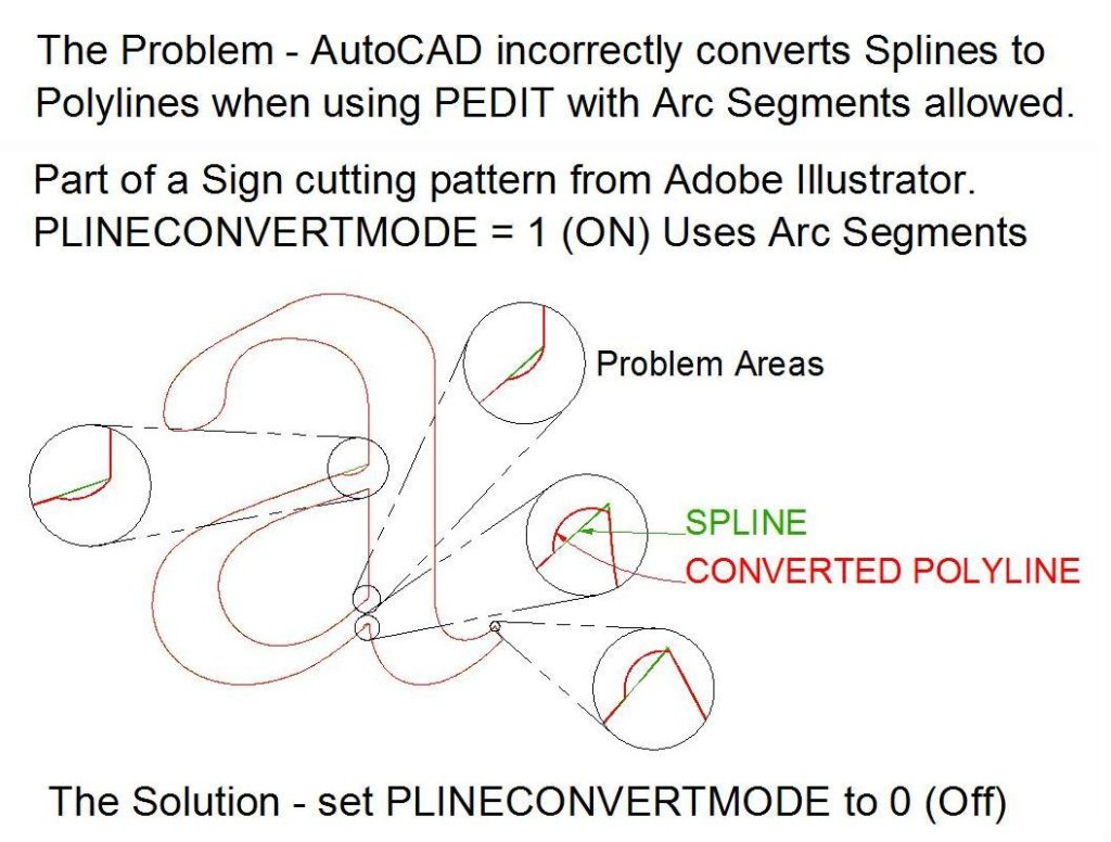
Figure 1 shows part of a sign cutting pattern from Adobe Illustrator. The PLINECONVERTMODE variable was set to 1 (on), indicating that the output polyline from the PEDIT command can include arcs. The original spline is green and the output polyline red. The callouts reveal how arcs are incorrectly added to the design, changing the design intent. This incorrect conversion is present in both AutoCAD and BricsCAD conversions.
The good news is that when PLINECONVERTMODE is set to 0 (off), indicating that the output polyline from the PEDIT command should not include arcs, none of these errors are present. So, for best results, set PLINECONVERTMODE to 0 (off).
Figure 1. Setting the PLINECONVERTMODE variable to 1 can introduce errors during spline conversion.
PRECISION
When converting splines with AutoCAD (2012 or later) or BricsCAD (v16.2 or later), the PRECISION setting controls how accurately the resulting polyline will fit the original spline: the higher the setting, the more accurate the conversion. The default PRECISION is set to 10; the value can be set to any integer between 0 and 99.
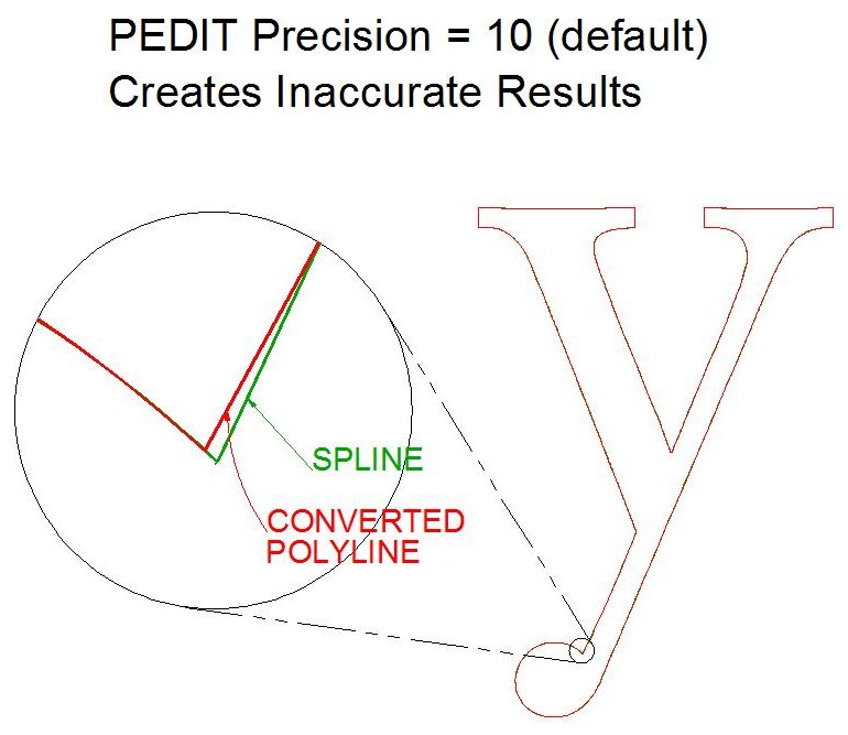
Here are some examples of the effect of a low PRECISION setting, 10, when using PEDIT. Figure 2 below illustrates how linework can be moved and figure 3 shows how curves can be overgeneralized, changing the design intent.
Figure 2. Setting PRECISION too low can move linework during conversion from splines to polylines.
Figure 3. Setting the PRECISION variable too low when converting splines to polylines can remove intended smoothness.
Setting the value is straightforward. Currently, the only way to set the PRECISION value is to run the PEDIT or SPLINEDIT (AutoCAD only), pick any spline entity and then input the desired Precision value. The setting will be remembered for the duration of the drawing session.
Determining the PRECISION value is a bit trickier, but in general use a higher rather than a lower value to maintain the accuracy of the design. Do note that a higher value will create many more vertices and possibly slowdown processing. But when the workflow is to Curvefit the resulting converted Polyline, more vertices is usually preferable because the shape is more accurately defined.
Using a higher setting for PRECISION is the resulting polyline will contain a lot more points. That, in turn, means the G-Code generated from that polyline could have too many points in the cutting path for the cutting machine to execute the job.
Adding just one additional mathematical conversion can solve that problem. TCI Software’s Curvefit will maintain the accuracy of the polyline and dramtically lower the number of points so the cutting machine can do its work efficiently.
Final Workflow
The workflow to convert a .AI file with splines to a usable polyline for G-Code creation involves two steps:
- Convert the splines into polylines that accurately fit the spline shape (using the guidance above).
- Curvefit the polylines (from BricsCAD, AutoCAD or other sources) with a tight tolerance.
TCI’s Curvefit optimizes polylines created with high or low PRECISION, so there’s no reason to degrade a .AI design with low PRECISION value when converting splines. To get the most accurate polyline to use in generating your G-Code, use your CAD package wisely, then use Curvefit.
Seeing is Believing
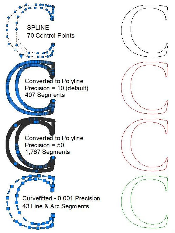
The resulting curvefitted polyline of the letter “C” in Figure 4 is actually 38% more compact than the original .AI spline. The processing noted shows how the 70 control points in the original spline were converted to just 43 lines and arcs in the final polyline. The original and the final match to within one part per 1000.
Figure 4. Processing an .AI file with AutoCAD and Curvefit.
Set PLINECONVERTMODE to zero (OFF); choose a high PRECISION before using PEDIT to convert splines to polylines. Then use Curvefit with a tight tolerance to optimize the polyline.
The original file included 70 controls points; the final polyline, just 43.
We offer a free fully functional demo of Curvefit for AutoCAD, BricsCAD, ZWCAD or the Stand-alone version which does not require a CAD platform.


