
The CoriMap Sampler is a collection of Block oriented tools originally developed for CoriMap, our 3D corridor mapping application. Even though they were originally developed to meet the needs of large corridor mapping projects, each tool is configurable to meet the needs of virtually any mapping application.
The CoriMap Sampler is now included in MapTools Pro
Automated Attribute Arrangement
Our Attribute Arrangement tool is a multi-purpose function for rearranging attributes associated with Blocks and Reordering groups of attributes in “Station Order”. The CoriMap Sampler version includes a command line interface with All of the capabilities of the CoriMap version (without batch capability) Click Here for more Details. {prod_cmap5.php}
Block Redefinition
With this tool, you can replace Block definitions and Block Insert with a predefined Gospel Block. Replacement blocks can maintain all characteristics during replacement: Scale, Rotation, Attribute Position, Rotation, Height and Justification. The CoriMap Block Redefinition also maintains all Object Data ( AutoCAD version only) and Hyperlinks. Click Here for more Details. {prod_blkredef.php}
Connecting Blocks with PTConnect
The PTConnect tool was built specifically to draw polylines between GPS Point Blocks, although it will work with any block. In some mapping projects, GPS Point data is collected for linear features such as the road centerline or a fenceline. These linear features must then be created by “connecting the dots”.
Another common requirement is to create a single piece of linework that connects several different block types. An example of this would be to draw a proposed Fiber Optic cable corridor route by connecting “points on” represented by the FORL Block and “Begin & End Bore” points represented by BORE Blocks. The PTConnect Dialog Box allows the selection of any number of block names for connection.
Copy / Scale Blocks
The CSBLKS tool was originally created to quickly produce a set of Scaled feature blocks to be used for different scale plots. The user specifies settings using a command line interface that allows:• the automatic selection of Blocks based on a Layer name spec • automatic Relayering of the copied Blocks • changing the Scale Factor for the Graphics portion of the Block • changing the Scale Factor for any Attributes associated with the Block
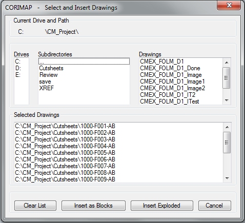
Select / Insert Blocks
The Select and Insert Drawings tool was created to automate the construction of System Drawings (a single drawing containing all drawings associated with a given pipeline or corridor system). A Dialog Box interface is provided to accommodate the selection of any drawing your computer can see. The selected drawings can then be Inserted as Blocks or Inserted and then Exploded.