
Polyline Restructuring and Point Set Builder
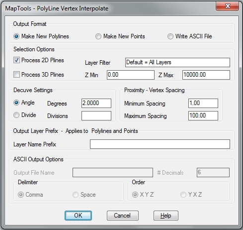
PTERP is an application that operates on 2D and 3D Polylines to create any of three outputs: make new Polylines with different vertex locations, make new Points inside of AutoCAD along the source polylines, or write ASCII disk files with XYZ point data for points along the souce polyline. PTERP is a full featured solution with unique controls for controlling the placement of new points along the polylines.
Automation Ready – PTERP can operate from the command line using a Dialog Box interface or as a part of more complex automation operations using MapTools Commander – process a drawing or a groups of drawings unattended.
Select Options
Several controls allow you to limit which selected polylines are processed. You can choose 2D only, 3D only or both. You can also filter out polylines based on the layer name (including wildcards). Minimum and Maximum Z setting can eliminate stray polylines that are not set to an elevation within the project limits.Polyline
Decurving
One of the most flexible methods for manipulating vertices along a polyline is to start with a polyline with “bulge” segments (curved polyline segments). This can be easily accomplished by “optimizing” the polyline with our Curvefit application. These curved segments can be decurved (points calculated along the curve – interpolated) using either of two methods:
Angle Mode – this will calculate new points along the curves with a set number of degrees spacing.
Divide Mode – this will divide every curve into a given number of parts and calculate the new points at those locations.
Proximity Control
Following the decurve process, the new point set is made up of the original vertices and the new points added by Decurving. This point set is then process to enforce Minimum and Maximum Proximity settings. Points cannot be closer together than the Minimum Proximity, nor farther apart that the Maximum Proximity. This process will create or delete points to enforce the settings and create the final point set.
Some Examples of its use: We will show examples using this polyline that contains both straight and curved segments.
Decurving – Minimum vertex spacing set small, Maximum vertex spacing set large and arc approximation set to 5 degrees. This maintains all vertices and replaces bulge vertices with straight ones.
Decurving with vertex reduction – we can set the minimum vertex spacing to reduce the number of vertices along the curves, or we could set the arc approximation to a higher value.
Generalize – if the minimum vertex spacing is increased, we get a generalized version – fewer vertices spaced farther apart.
Normalize – When the Minimum and Maximum vertex spacing is set to the same value, we get evenly spaced vertices.
Densify – We can get more than we started with if we set the Minimum vertex spacing to a low value – more vertices spaced closer together.